Tuesday, June 13, 2017

LAQ Blog


 Through Genius Hour, I have learned quite a bit about how our eyes and corrective lenses work. Here's an overview of the key information that I've learned:

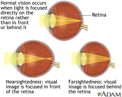
  • There are three main parts of the eye that a responsible for producing an image: the front (pupil/cornea, allows light to enter), the lens (focuses light), and the retina (converts light into nerve signals). This is sort of like a camera/lens. The pupil is like the aperture blades, the lens like the focusing mechanism, and the retina like the image sensor/film plane in the body of the camera.
  • Poor vision is often caused by irregularities in eye shape. As a result, the lens cannot change shape enough (in a process called accommodation) to focus the light onto the retina. Instead, the image is formed in front of retina (nearsightedness) or behind retina (farsightedness). 
  • The solution to this is to refract the light before it enters the eye, so that the eye has enough power to focus the light onto retina. This is often done through corrective lenses such as eyeglasses and contacts.

For my podcast, I decided to concentrate on contact lenses because of time constraints. Here are a list of sources that I used to produce my podcast:


As I mentioned in my podcast, if we had more time, I would have loved to learn a bit more about topics such as astigmatisms, and all the prescription numbers corresponding to them. I also have some questions about different kinds of glasses, and other ways of correcting vision (i.e., laser eye surgery).


Feedback for "Genius Hour:"

Honestly, I'm a bit disappointed. I really like the concept of "Genius Hour" in that you can explore a scientific topic, but I didn't like how it was executed. It felt too constrained

The main factor was the mandatory blog posts. The grade should just be for the final presentation/product. The blog posts didn't help because they were just a repeat of notes, and wasted time that could have been spent on learning new information on the actual topic. The blog posts also ensured that you could not change your topic, as each blog post had to refer to the previous as an extension.

Also, the requirement of a podcast offered yet another constraint. For a topic that's literally about eyes and vision, a visual aid would have allowed for better explanations and a better understanding. I'm sure many others would have also benefited from a more free format.

I feel like a better alternative could be just allowing students to pick whatever topic they like, research it, and then deliver some sort of presentation in a time frame of maybe 1-2 weeks. This allows students to work at their own pace, and create whatever product they prefer.

Thursday, April 6, 2017

Project Update I

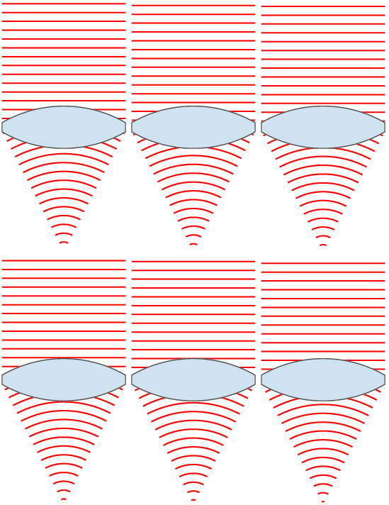
My original idea was to research all different kinds of lenses ranging from the human eye to telescopes. However, after doing some basic research, I realized that learning about such a large spectrum would limit how in-depth my research would be. Instead, I have decided to focus (heh) on the lens of the human eye in terms of its mechanics and how it can be adjusted (i.e., eyeglasses and contact lenses).

I will strive to answer the questions that I proposed in my first post:
  • How do the lenses in our eyes change shape to maintain focus?
  • What do the numbers in eye prescriptions mean?

So far, I have only been able to do some research on the basic concepts behind lenses and the lenses in a human eye:
  • Lenses focus rays of light because light travels more slowly in the lens than in the air, which allows the light the "bend" and focus.
animation showing the basic idea behind lenses
  • The focal point or principal focus (represented by "F") is where the light beams converge.
  • The focal length (represented by "f") is the distance from the center of the lens to the focal point.
graphic showing the focal point (F) and focal length (f)
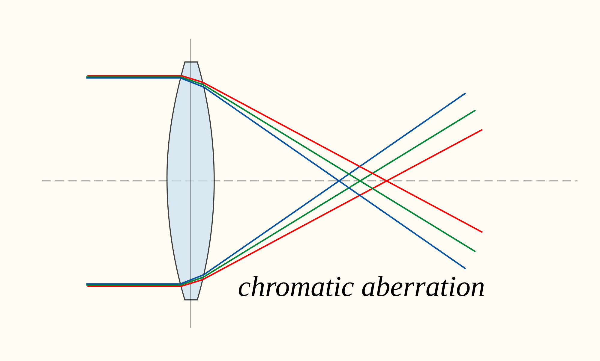
  • Often, multiple lenses are used in more precise equipment such as cameras and microscopes to correct for aberrations. Aberration is a term used for when a patch of light is produced instead of a single point.
    • The line that runs through the centers of these lenses is known as the principal axis.
graphic demonstrating a kind of aberration
picture of chromatic aberration
  •  The human eye is able to focus through tightening/relaxing of the ciliary muscle. This muscle stretches and compresses the lens within the eye, which will bend light differently depending on the shape, which allows the eye to focus.
graphic showing how the eye focuses
The two best sources I have found so far are the Encyclopedia Britannica article on optical lenses and a page on "Accommodation" of the human eye on HyperPhysics by Georgia State University.

My questions to answer for next time are:
  • What do the numbers in eye prescriptions mean? 
  • Why do some of us require corrective lenses (i.e., why do we need glasses/contacts?)
  • How do corrective lenses work with the human eye?

Wednesday, March 8, 2017

Circuit Challenge #25

Circuit Challenge #25


Circuits are great fun. I even made my own.

The Setup

Total voltage: 24 V
The five resistors have resistances that are the prime numbers greater than or equal to 5.

Total Resistance

The first logical step would be to calculate the total resistance. The equations for calculating equivalent resistances are:
  • in series: Req = R1 + R2 + R3 + …
  • in parallel: 1/Req = 1/R1 + 1/R2 + 1/R3 + …

Because this circuit is a compound circuit, we will be using both of these equations. First, we would want to calculate the Req of the parallel circuit, which, altogether, can then be treated as “in series” with R1 and R2:

Total Current

Once we know the total resistance, we can calculate the total current because we already know the total voltage. In order to calculate the total current, we will use Ohm’s Law:
  • V = I * R; (voltage = current * resistance) 
    • solved for I, it becomes: I = V/R


Individual Resistors - In Series

We can begin to calculate the voltage and current across each individual resistor now that we know the total voltage, total resistance, and total current.

We’ll start with the resistors in series: R1 and R2. In series, the current is the same everywhere (Ibattery = I1 = I2 = I3 = …). We can use the given R and I (which is equal to the total current) to calculate the voltages across each resistor with Ohm’s Law.
We can fill this information into our circuit diagram.

Individual Resistors - In Parallel

The whole parallel circuit can be treated as a single equivalent resistor that is in series with R1 and R2. In series, the total voltage is equivalent to the sum of all the individual voltages across each resistor (Vbattery = V1 + V2 + V3 + …).

Vbattery = V1 + V2 + Vparallel
24 = 7.31 + 10.234 + Vparallel
Vparallel = 6.456 V

In a parallel circuit, the voltage is the same everywhere (Vbattery = V1 = V2 = V3 = …), so we know the voltages across R3, R4, and R5 are all 6.456 V. We also know the resistances, so we can use Ohm’s Law (V = I * R or I = V/R) to calculate the current that passes through each of these resistors.

R3
R = 11 ohms
V = 6.456 V
I = V/R = 0.587 A
R4
R = 13 ohms
V = 6.456 V
I = V/R = 0.497 A
R5
R = 17 ohms
V = 6.456 V
I = V/R = 0.380 A

We can check that these currents are correct by adding them up to make sure they are approximately equal to the total current:

0.587 + 0.497 + 0.380 = 1.464 A ~ 1.462 A :)

All Done

We can now complete our circuit diagram:
Done. Done. Done, Heidi, SHHHHHHHHHHHHHHHHHHH. #fanggang 

Extra

Here’s a screenshot of the circuits made on an iPad:
 

We could also modify the circuit slightly. For example, we can make R3 have a resistance of 110 ohms. If we were to do this, and recalculated everything, we would observe the following:
  • the Req of the parallel circuit would be larger
    • the total resistance of the whole circuit would also be larger
  • the total current would be smaller because resistance and current are inversely related according to Ohm’s Law (V = I * R)
    • the currents across all resistors would be smaller
    • if these resistors were light bulbs, they would all be dimmer
  • the voltage across R1 and R2 would decrease because of the smaller current
  • the voltage across the parallel circuit (R3, R4, R5) would increase in order to make the total voltage = 24 V

Wednesday, March 1, 2017

KWH Blog

Lenses allow humans to share our experiences through photography, explore the building blocks of life with microscopes, probe the depths of our universe with telescopes, and, most importantly, to see the world clearly.


TOPIC
The physics/concepts behind lenses such as eye lenses, camera lenses, microscope/telescope lenses, soft contact lenses, hard contact lenses, and eyeglasses.

KIND OF KNOW
My understanding is that lenses work by refracting light in a way that allows light to be focused to a certain point. For example, the lenses on cameras bend light to make it hit the sensor within the body of the camera.


WANT TO KNOW
How is light "bent?"

How do the lenses in our eyes change shape to maintain focus?
What do the numbers in eye prescriptions mean?

What do the different focal lengths of camera lenses mean?
Why are multiple elements needed within a camera lens?

Why is glass used for lenses?
What is an "index of refraction?"


HOW TO FIND ANSWERS
I will find some books/online sources about optics in physics. For subjects relating to eyes, contact lenses, or glasses, I can probably look for sources for optometry. For camera lenses and microscope lenses, I can look for information from photography-based sources.

Wednesday, January 18, 2017

Bumper Design

Impulse is the change in momentum, as expressed in the equation: I = Δp = pf - pi. Because of this, the unit for impulse is the same as the unit for momentum: kg-m/s. Impulse can also be defined as the product of a force and the time over which the force was applied, i.e., I = F * t.

We learned that in a collision where the impulse (or change in momentum) is the same, increasing the time over which the collision occurs will decrease the force experienced by the colliding objects. For example, a car going at a given velocity crashing into a brick wall will have the same impulse as the same car at same velocity crashing into a large air bag. However, the change in momentum will be over a longer time, which means the force experienced is less in the case of the air bag: I = Δp = F * t = F’ * t’; if F * t = F’ * t’ and t’ > t, then F’ < F.

In class, we demonstrated this principle by constructing bumpers for little carts, and measuring the forces experienced by the cart. For this experiment, we were given a plastic bag, tape, and a few sheets of paper. Because the force and time are inversely related in the case of impulse, we knew that we had to maximize the time over which the cart went from moving (non-zero momentum) to stop (zero momentum).

After some thought, we determined that the best way to achieve this was through maximizing the ability for the bumper to compress slowly. We knew that, with our given materials, the best way would have been to just crumple paper in a way that leaves a good volume of air between the folds, and then stick it in the bag. However, we decided to try a different approach which involved rolling strips of paper into little tubes. This created a “spring” effect. These springs were then wrapped in paper, which was wrapped in a plastic bag.

The idea was that the springs would provide enough resistance to not have the bumper collapse completely, but they would also be malleable enough to collapse when the cart collided. Also, because the tubes were separate from each other, we had hoped that the tubes would slide past each other, which would also increase the ability of the bumper to collapse.

TRIAL ONE

image of cart in Trial One
video of cart in Trial One
graph of Trial One

Trial One resulted in a force of approx. 1.49 N being experienced by the cart. This was pretty good, however, we knew that it could be better. We realized that our bumper did not collapse as much as we would have liked. For our redesign, we slightly unrolled the tubes to make the diameters larger, which resulted in an overall weaker spring effect. We also removed a few tubes to allow for more air/movement between the tubes.

TRIAL TWO
image of cart in Trial Two

video of cart in Trial Two
graph of Trial Two

Our redesign slightly improved our results, as the experienced force dropped to approx. 1.23 N. If we were to redesign again, we would have decreased the rigidity of the tubes even further.